
Inserting parts
Inserting a fitting by hand
Usually "Generate 3D" places the fittings itself. You insert a single part – elbow, tee, reducer, coupling – by hand: it hangs at the cursor and snaps to pipe ends and corners. You decide where it sits and how far it stands off the pipe.
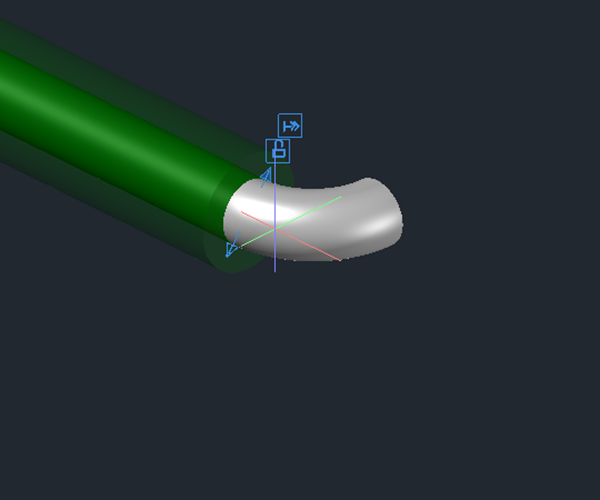
- On the Pipe page of the panel choose Fitting under "Insert as", select the fitting and click Insert.
- Move the cursor to a pipe end or a corner: the part docks (1) – only if nominal size and medium match the pipe; otherwise the cross tells you what does not fit. Elbows and tees snap to the corner, reducers and couplings break into the pipe.
- At the docking cross (2): lock = hold (F), arrow symbol = pull away (Z) – a pipe is created in between. Type a length and press Enter.
- Rotate with R or the arrow keys. The Space key shows the connections of the part to click.
- A click inserts it, and the next part hangs at the cursor. Enter = finish, Esc = cancel.
Inserting a part into a pipe
Valves, symbols, products and custom components break into the pipe: the pipe is interrupted at that point and runs through the part.
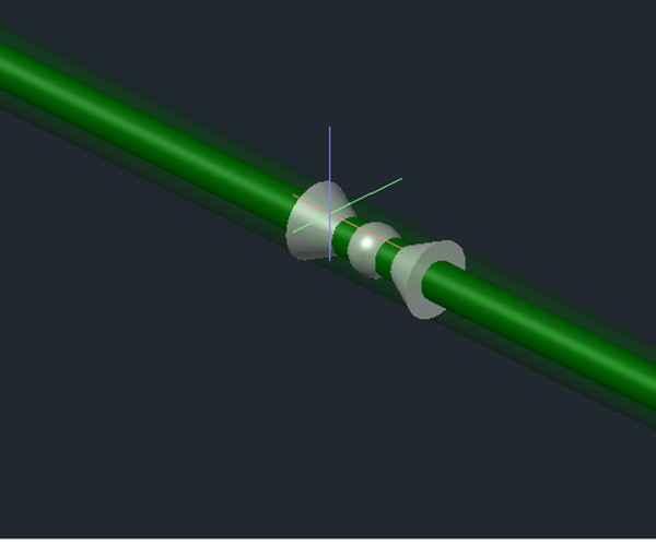
- Choose the part in the panel (page Symbols, Products or Custom components) and click Insert.
- Point at a pipe until the part aligns with it, and click (1) – step 1 of 2.
- Slide the part along the pipe to the right position and click (2) – step 2 of 2. Arrow left/right turns it round, Esc goes back to step 1.
- Next to a pipe it docks at a free connection (F holds it there) or is inserted freely – A sets a distance to a point.
- The Space key shows the connections to click, R rotates. Enter = finish, Esc = cancel.
Inserting a mounted instrument
Pressure gauges, thermometers and air vents sit on the pipe – the pipe runs through underneath.
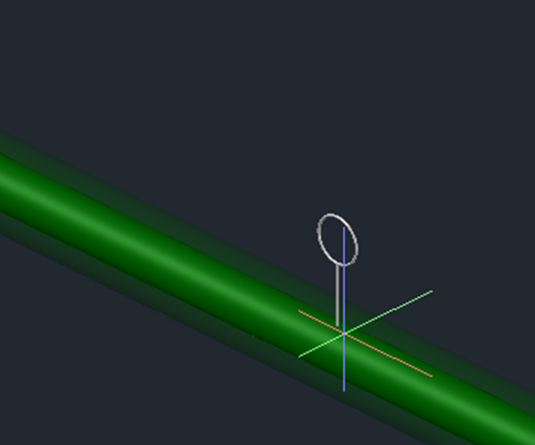
- On the Products page choose the neutral instrument (pressure gauge, thermometer, automatic air vent) and click Insert.
- Click the pipe the instrument should sit on (1).
- Slide the instrument along the pipe (2). The arrow keys turn it around the pipe in steps, R rotates with the mouse, D takes a typed angle.
- A click inserts it, Esc goes back to choosing the pipe, Enter = finish.
Custom symbols: defining the connections
With the symbol wizard (Symbols page) you turn a drawn valve into your own symbol. It needs a centre and one point per connection – that is how LuaCAD later places it in the pipe.
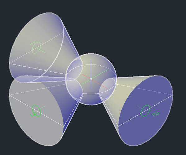
- Draw the body and the lines of the symbol, then start the symbol wizard.
- Click the centre of the symbol (1) – this is where it will sit on the pipe axis.
- Click the end of each connection one after the other (2, 3, 4). The direction runs from the centre to the click. An in-line symbol has two connections, one with a branch three.
- Enter = finish, the symbol is saved and appears in the list. Esc = cancel – nothing is changed.