
Connections
Placing a pipe connection
A pipe connection marks where a pipe is to start – for example the cold and hot water connections of a wash basin. The connections of a template hang at the cursor together; their height is the installation level of the panel plus the offset of the template.
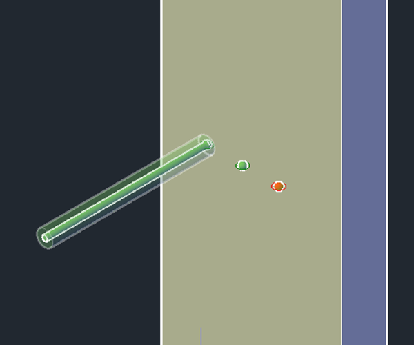
- On the Risers/connections page choose a connection template (a single connection or, for example, a wash basin) and click Insert riser/connections. With "Show the dialog before inserting" ticked you check the values first.
- Click the insertion point (1). The Space key switches the grip point (insertion point or one connection), R rotates, A sets a distance to a reference point.
- All connections of the template come together (2) – several form a set that can be selected as one.
- The next set hangs at the cursor right away. Esc = back to the template or finish.
Later a pipe starts exactly at a connection (3): put the start on the connection – medium and nominal size come from it.
Defining the connections of a custom component
A custom component (a DWG, for example a pump from a manufacturer catalog) only docks to pipes once it has connections. Each connection is a coloured marker at an opening: a circle on a pipe, a cross on a duct. The colour is the connection type.
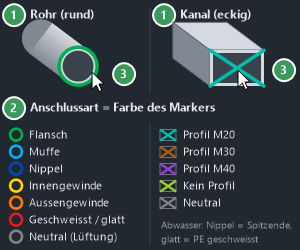
- Open the DWG of the component and start the custom component wizard (Custom components page, "Define connections").
- Choose the shape: "round (pipe)" with DN or "rectangular (duct)" with width and height – type it or pick it with the crosshair.
- Choose the connection type – it sets the colour of the marker (flange, press socket, thread, welded …).
- Click Place connections and point at a round edge or a duct opening: the marker aligns itself, each click places one.
- Esc returns to the wizard – for another type, to change something or for the properties (manufacturer, article number).
- Finally save the drawing: only then does the component know its connections.